The OBD2 connector is a standardized interface in your vehicle that allows access to its self-diagnostic system, providing valuable data for troubleshooting and maintenance; CAR-TOOL.EDU.VN provides comprehensive information and tools related to this vital component. By understanding the OBD2 protocol, diagnostic trouble codes, and real-time data, you gain insights into your vehicle’s health. Explore our resources to enhance your knowledge of automotive diagnostics and repair tools, ensuring you’re well-equipped for any automotive challenge.
Contents
- 1. Understanding the OBD2 Connector
- 1.1. OBD2 Compliance and Compatibility
- 1.2. History and Evolution of OBD2
- 1.3. Future Trends in OBD Technology
- 2. Exploring OBD2 Standards
- 2.1. The OBD2 Connector Explained
- 2.2. Distinguishing Between Type A and Type B Connectors
- 2.3. OBD2 and CAN Bus Integration
- 3. CAN Identifiers in OBD2 Communication
- 3.1. Understanding Proprietary CAN Protocols
- 3.2. Validating Bit-Rate and ID
- 3.3. Exploring Lower-Layer Protocols
- 4. Message Transport and Structure
- 4.1. The OBD2 Diagnostic Message
- 4.2. Diving into OBD2 Modes and PIDs
- 4.3. Parameter IDs (PIDs) in OBD2
- 5. Logging and Decoding OBD2 Data
- 5.1. Configuring PID Requests
- 5.2. Decoding Raw OBD2 Data
- 5.3. Multi-Frame Communication
- 6. Real-World Examples
- 6.1. Example: Vehicle Identification Number (VIN)
- 6.2. Diagnostic Trouble Codes (DTCs)
- 6.3. Data Logging Use Cases
- 7. Get Expert Assistance at CAR-TOOL.EDU.VN
- 7.1. Comprehensive Tool Selection
- 7.2. Expert Support and Guidance
- 7.3. Stay Informed with Our Resources
- 8. Contact Us Today
- 9. Frequently Asked Questions (FAQ)
1. Understanding the OBD2 Connector
The On-Board Diagnostics version 2 (OBD2) connector serves as the gateway to your vehicle’s self-diagnostic system. It’s a standardized protocol that enables the extraction of diagnostic trouble codes (DTCs) and real-time data. When the malfunction indicator light appears on your dashboard, it signals an issue that an OBD2 scanner can diagnose through this connector. Mechanics connect the OBD2 reader to the 16-pin OBD2 connector, typically found near the steering wheel, and send requests to the car, receiving responses that include speed, fuel level, and DTCs.
This image illustrates the OBD2 connector being used with a scan tool to diagnose vehicle issues.
1.1. OBD2 Compliance and Compatibility
Most modern vehicles support OBD2, running on the CAN bus system. However, older cars with a 16-pin OBD2 connector might not fully support OBD2. Determining compliance involves checking where and when the vehicle was bought. In the United States, OBD2 has been mandatory for cars and light trucks since 1996. The OBD2 protocol was initially developed in California for emission control purposes, with the California Air Resources Board (CARB) mandating OBD in new cars from 1991 onward.
1.2. History and Evolution of OBD2
The OBD2 standard was recommended by the Society of Automotive Engineers (SAE), standardizing DTCs and the OBD connector across manufacturers via SAE J1962. The implementation of OBD2 standards occurred gradually:
- 1996: Mandatory in the USA for cars and light trucks.
- 2001: Required in the EU for gasoline cars.
- 2003: Required in the EU for diesel cars (EOBD).
- 2005: Required in the US for medium-duty vehicles.
- 2008: US cars must use ISO 15765-4 (CAN) as the OBD2 basis.
- 2010: Required in US heavy-duty vehicles.
1.3. Future Trends in OBD Technology
The future of OBD2 is evolving with trends like OBD3, which incorporates telematics for remote diagnostics and emissions testing. OBD3 aims to add a small radio transponder to vehicles, allowing VIN and DTCs to be sent via WiFi to a central server for checks. This offers convenience and cost savings, but raises surveillance concerns. While OBD2 was designed for emission controls, it’s now used for real-time data generation. However, there are proposals to limit third-party access to OBD2 data while driving, giving manufacturers more control over automotive data.
2. Exploring OBD2 Standards
OBD2 is a higher-layer protocol like a language, while CAN is the communication method (like a phone). This parallels other CAN-based protocols like J1939, CANopen, and NMEA 2000. The OBD2 standards define the connector, lower-layer protocols, and parameter IDs (PIDs). The standards can be viewed in a 7-layer OSI model, with SAE and ISO standards covering various layers, reflecting OBD definitions in the USA (SAE) and EU (ISO).
2.1. The OBD2 Connector Explained
The 16-pin OBD2 connector, specified in SAE J1962 / ISO 15031-3, enables easy access to vehicle data. This connector is typically near the steering wheel. Pin 16 provides battery power, and the OBD2 pinout depends on the communication protocol. CAN bus is the most common lower-layer protocol, connecting to pins 6 (CAN-H) and 14 (CAN-L). In practice, both Type A and Type B OBD2 connectors exist, with Type A in cars and Type B in medium and heavy-duty vehicles.
This diagram shows the pinout of a Type A OBD2 connector, highlighting the function of each pin.
2.2. Distinguishing Between Type A and Type B Connectors
Type A and Type B connectors share similar pinouts, but differ in power supply outputs (12V for Type A, 24V for Type B). Baud rates also vary, with cars typically using 500K and heavy-duty vehicles using 250K (though recent support for 500K is growing). To differentiate them, Type B OBD2 connectors have an interrupted groove in the middle.
2.3. OBD2 and CAN Bus Integration
Since 2008, CAN bus has been the mandatory lower-layer protocol for OBD2 in US cars, according to ISO 15765. ISO 15765-4 (Diagnostics over CAN or DoCAN) restricts the CAN standard (ISO 11898), standardizing the CAN interface for test equipment with a focus on the physical, data link, and network layers. The CAN bus bit-rate must be 250K or 500K, and CAN IDs can be 11-bit or 29-bit. Specific CAN IDs are used for OBD requests/responses, the diagnostic CAN frame data length must be 8 bytes, and the OBD2 adapter cable must be max 5 meters.
3. CAN Identifiers in OBD2 Communication
All OBD2 communication involves request/response messages. In most cars, 11-bit CAN IDs are used, with the ‘Functional Addressing’ ID being 0x7DF. This asks all OBD2-compatible ECUs if they have data to report. CAN IDs 0x7E0-0x7E7 are used for ‘Physical Addressing’ requests from specific ECUs. ECUs respond with 11-bit IDs 0x7E8-0x7EF, with 0x7E8 (ECM, Engine Control Module) being the most common. In some vehicles, OBD2 communication uses extended 29-bit CAN identifiers instead of 11-bit CAN identifiers, with a ‘Functional Addressing’ CAN ID of 0x18DB33F1.
3.1. Understanding Proprietary CAN Protocols
Your car’s electronic control units (ECUs) don’t rely on OBD2 to function; each original equipment manufacturer (OEM) implements their own proprietary CAN protocols, specific to the vehicle brand, model, and year. Connecting a CAN bus data logger to the OBD2 connector may show the OEM-specific CAN data, but many newer cars block access to this data, only enabling OBD2 communication. Think of OBD2 as an extra higher-layer protocol in parallel to the OEM-specific protocol.
3.2. Validating Bit-Rate and ID
OBD2 may use two bit-rates (250K, 500K) and two CAN ID lengths (11-bit, 29-bit), resulting in 4 potential combinations. Modern cars commonly use 500K and 11-bit IDs, but external tools should verify this systematically. ISO 15765-4 recommends a systematic initialization sequence to determine the combination, leveraging that OBD2-compliant vehicles must respond to a specific mandatory OBD2 request. Newer versions of ISO 15765-4 account for OBD communication via OBDonUDS rather than OBDonEDS.
3.3. Exploring Lower-Layer Protocols
While CAN is the primary basis for OBD2, older cars may use other lower-layer protocols:
- ISO 15765 (CAN bus): Mandatory in US cars since 2008.
- ISO14230-4 (KWP2000): Common in 2003+ cars, especially in Asia.
- ISO 9141-2: Used in EU, Chrysler, and Asian cars in 2000-04.
- SAE J1850 (VPW): Mostly in older GM cars.
- SAE J1850 (PWM): Mostly in older Ford cars.
4. Message Transport and Structure
All OBD2 data is communicated on the CAN bus through ISO-TP (ISO 15765-2), which enables communication of payloads exceeding 8 bytes, necessary for extracting the Vehicle Identification Number (VIN) or Diagnostic Trouble Codes (DTCs). ISO 15765-2 provides segmentation, flow control, and reassembly. Often, OBD2 data fits in a single CAN frame, using a ‘Single Frame’ (SF) where the 1st data byte contains the payload length, leaving 7 bytes for OBD2 communication.
4.1. The OBD2 Diagnostic Message
An OBD2 message includes an identifier, data length (PCI field), and data split into Mode, parameter ID (PID), and data bytes. As an example, consider a request/response for ‘Vehicle Speed’. An external tool sends a request to the car with CAN ID 0x7DF and 2 payload bytes: Mode 0x01 and PID 0x0D. The car responds via CAN ID 0x7E8 and 3 payload bytes, including the Vehicle Speed value in the 4th byte.
4.2. Diving into OBD2 Modes and PIDs
There are 10 OBD2 diagnostic services (modes). Mode 0x01 shows real-time data, while others show/clear diagnostic trouble codes (DTCs) or freeze-frame data. Vehicles don’t have to support all modes and may support OEM-specific modes. In OBD2 messages, the mode is in the 2nd byte; in the response, 0x40 is added to the mode.
This visual breaks down the 10 OBD2 modes, highlighting their functions, such as displaying current data, freeze frame data, and clearing DTCs.
4.3. Parameter IDs (PIDs) in OBD2
Each OBD2 mode contains parameter IDs (PIDs). For example, mode 0x01 contains ~200 standardized PIDs with real-time data on speed, RPM, and fuel level. However, vehicles only support a subset. If an emissions-related ECU supports any OBD2 services, it must support mode 0x01 PID 0x00. In response to this PID, the vehicle ECU informs whether it supports PIDs 0x01-0x20.
5. Logging and Decoding OBD2 Data
To log OBD2 data, tools like the CANedge CAN bus data logger can be used. The CANedge allows configuring custom CAN frames for OBD2 logging and can be connected to vehicles via an OBD2-DB9 adapter cable. As discussed, ISO 15765-4 describes how to determine which bit-rate and IDs a vehicle uses. Test this by sending CAN frames at 500K and checking for success. Most 2008+ non-EV cars support 40-80 PIDs via a 500K bit-rate, 11-bit CAN IDs, and the OBD2/OBDonEDS protocol.
5.1. Configuring PID Requests
After identifying supported PIDs, configure your transmit list with PIDs of interest, using ‘Physical Addressing’ request IDs (e.g., 0x7E0) to avoid multiple responses. Add 300-500 ms between each request to avoid overwhelming ECUs, and use triggers to stop transmitting when the vehicle is inactive to conserve battery.
5.2. Decoding Raw OBD2 Data
To analyze data, decode the raw OBD2 data into ‘physical values’ using information from ISO 15031-5/SAE J1979 or a free OBD2 DBC file, which makes it easy to DBC decode raw data in most CAN bus software tools. Decoding OBD2 data is more complex than regular CAN signals, requiring the use of CAN ID, OBD2 mode, and OBD2 PID to identify the signal.
5.3. Multi-Frame Communication
Multi-frame OBD2 communication uses flow control frames, which can be implemented by transmitting a static flow control frame 50 ms after the initial request frame. Multi-frame responses require CAN software/API tools that support ISO-TP. To extract the Vehicle Identification Number (VIN) using OBD2 requests, use mode 0x09 and PID 0x02. The tester tool sends a Single Frame request with the PCI field, request service identifier, and PID.
6. Real-World Examples
Multi-frame OBD2 communication is exemplified by extracting the Vehicle Identification Number (VIN). To extract the VIN from a vehicle using OBD2 requests, use mode 0x09 and PID 0x02.
6.1. Example: Vehicle Identification Number (VIN)
The VIN is often relevant to telematics and diagnostics. The tester tool sends a Single Frame request with the PCI field (0x02), request service identifier (0x09), and PID (0x02).
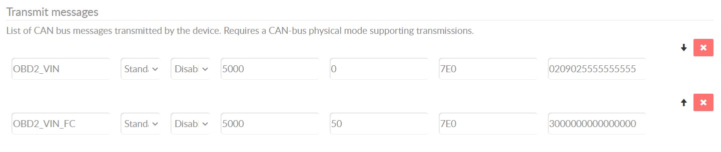 OBD2 Multi-Frame Request for VIN
6.2. Diagnostic Trouble Codes (DTCs)
You can use OBD2 to request emissions-related Diagnostic Trouble Codes (DTCs) from using mode 0x03, i.e. ‘Show stored Diagnostic Trouble Codes’. The ECU(s) will respond with the number of DTCs they have stored, with each DTC taking up 2 data bytes. As a result, multi-frame responses are necessary when more than 2 DTCs are stored. The 2-byte DTC value is split into two parts, defining the ‘category’ and a 4-digit code.
6.3. Data Logging Use Cases
OBD2 data from cars and light trucks can be used in various use cases:
- Logging data from cars: To reduce fuel costs, improve driving, test prototype parts, and for insurance purposes.
- Real-time car diagnostics: To stream human-readable OBD2 data in real-time for diagnosing vehicle issues.
- Predictive maintenance: To monitor cars and light trucks via IoT OBD2 loggers in the cloud to predict and avoid breakdowns.
- Vehicle blackbox logger: As a ‘blackbox’ for vehicles or equipment, providing data for disputes or diagnostics.
7. Get Expert Assistance at CAR-TOOL.EDU.VN
Navigating the complexities of OBD2 systems can be challenging. At CAR-TOOL.EDU.VN, we offer expert guidance and a wide range of tools to help you understand and utilize OBD2 technology effectively. Whether you’re a seasoned mechanic or a car enthusiast, our resources can enhance your diagnostic capabilities and keep your vehicle running smoothly.
7.1. Comprehensive Tool Selection
Discover a curated selection of OBD2 scanners, adapters, and data loggers at CAR-TOOL.EDU.VN. Our tools are designed for both professional and DIY use, ensuring you have the right equipment for any diagnostic task.
7.2. Expert Support and Guidance
Our team of automotive experts is available to provide personalized support and answer your questions. Contact us for advice on selecting the right tools, understanding diagnostic codes, and troubleshooting vehicle issues.
7.3. Stay Informed with Our Resources
CAR-TOOL.EDU.VN is your go-to source for the latest information on OBD2 technology, diagnostic techniques, and automotive maintenance tips. Explore our articles, tutorials, and guides to stay ahead of the curve.
8. Contact Us Today
Ready to enhance your automotive diagnostic capabilities? Contact CAR-TOOL.EDU.VN today for expert assistance and top-quality tools.
Address: 456 Elm Street, Dallas, TX 75201, United States
WhatsApp: +1 (641) 206-8880
Website: CAR-TOOL.EDU.VN
We look forward to helping you unlock the full potential of your vehicle’s diagnostic system. Reach out now and let us assist you with your automotive needs.
9. Frequently Asked Questions (FAQ)
Q1: What is an OBD2 connector?
An OBD2 connector is a standardized interface in vehicles that allows access to the vehicle’s self-diagnostic system for extracting diagnostic trouble codes (DTCs) and real-time data.
Q2: Where is the OBD2 connector located in my car?
The OBD2 connector is typically located near the steering wheel, but it may sometimes be hidden behind a panel or cover.
Q3: Does my car support OBD2?
Most modern vehicles support OBD2, especially those manufactured after 1996 in the United States and after 2001/2003 in Europe.
Q4: What can I do with an OBD2 scanner?
An OBD2 scanner can read diagnostic trouble codes (DTCs), monitor real-time data such as speed and fuel level, and provide insights into your vehicle’s health.
Q5: What is a diagnostic trouble code (DTC)?
A DTC is a code stored in the vehicle’s computer that indicates a specific problem or malfunction in the vehicle’s systems.
Q6: How do I interpret OBD2 codes?
OBD2 codes can be interpreted using online OBD2 code lookup tools or by consulting a professional mechanic.
Q7: What is the CAN bus system in OBD2?
The CAN (Controller Area Network) bus system is a communication protocol used in modern vehicles to allow different electronic control units (ECUs) to communicate with each other.
Q8: What are OBD2 PIDs?
OBD2 PIDs (Parameter IDs) are codes used to request specific data from the vehicle’s computer, such as engine speed, coolant temperature, or fuel level.
Q9: Can I clear OBD2 codes myself?
Yes, you can clear OBD2 codes using an OBD2 scanner, but it’s important to understand the underlying issue causing the code before clearing it.
Q10: Where can I find reliable OBD2 tools and information?
You can find reliable OBD2 tools and information at CAR-TOOL.EDU.VN, which offers a wide range of tools and expert guidance for automotive diagnostics.
By providing detailed information about the OBD2 connector, its functions, and the resources available at CAR-TOOL.EDU.VN, this article aims to assist readers in understanding and utilizing their vehicle’s diagnostic system effectively. We encourage you to explore our website and contact us for any further assistance or queries. Let CAR-TOOL.EDU.VN be your trusted partner in automotive diagnostics and repair.