Oscilloscope Car Diagnostics can significantly improve your auto repairs by providing a detailed view of electrical signals, allowing for more accurate and efficient troubleshooting. CAR-TOOL.EDU.VN offers comprehensive resources to help you master this essential skill, ensuring you can quickly identify and resolve complex automotive issues. Utilizing an automotive lab scope, ignition diagnostics, and automotive waveform analysis will enhance your diagnostic capabilities.
1. What is Oscilloscope Car Diagnostics?
Oscilloscope car diagnostics involves using an oscilloscope, also known as a lab scope, to visualize and analyze electrical signals in a vehicle’s electronic systems, enabling precise and efficient troubleshooting. The oscilloscope displays voltage changes over time, creating waveforms that provide insights into the performance of sensors, actuators, and other components. According to a study by the National Institute for Automotive Service Excellence (ASE), technicians using oscilloscopes can diagnose electrical issues up to 40% faster than those relying solely on traditional methods.
- Key Components: Oscilloscopes, probes, and vehicle-specific adapters.
- Typical Applications: Diagnosing sensor malfunctions, ignition problems, and communication network issues.
- Benefits: Improved accuracy, reduced diagnostic time, and enhanced understanding of complex systems.
2. Why Use an Oscilloscope for Car Diagnostics?
Using an oscilloscope for car diagnostics offers unparalleled precision and efficiency in identifying electrical issues, leading to quicker and more accurate repairs. Unlike basic scan tools that only read diagnostic trouble codes (DTCs), an oscilloscope allows you to visualize the actual electrical signals flowing through a vehicle’s systems. Automotive expert Dave Hobbs notes that “an oscilloscope is like a doctor’s stethoscope for your car, allowing you to ‘listen’ to the electrical heartbeat of the vehicle.”
- Visualize Electrical Signals: See the actual voltage changes over time, revealing signal anomalies that a scan tool might miss.
- Identify Intermittent Problems: Capture transient events and intermittent faults that are difficult to detect with other methods.
- Verify Sensor and Actuator Performance: Ensure components are functioning correctly by analyzing their waveforms under various operating conditions.
- Troubleshoot Communication Networks: Diagnose issues with CAN bus, LIN bus, and other communication protocols by examining the data signals.
- Reduce Diagnostic Time: Pinpoint the root cause of electrical issues faster, reducing labor costs and improving customer satisfaction.
3. Who Benefits from Oscilloscope Car Diagnostics?
Oscilloscope car diagnostics benefits a wide range of automotive professionals, from novice technicians to seasoned shop owners, by enhancing diagnostic accuracy and efficiency. Whether you’re a young technician looking to expand your skills, an experienced mechanic seeking to improve your diagnostic capabilities, or a shop owner aiming to boost productivity, understanding and using an oscilloscope can significantly enhance your ability to tackle complex automotive issues.
- Young Technicians (18-35): Gain expertise in advanced diagnostics, making you a valuable asset to any shop.
- Experienced Mechanics (35-55): Improve diagnostic accuracy and efficiency, reducing repair times and increasing customer satisfaction.
- Shop Owners/Managers (40-60): Enhance shop productivity by equipping technicians with the tools and knowledge to diagnose complex electrical issues quickly.
- Automotive Instructors: Equip students with in-depth knowledge of vehicle systems.
4. Where Can You Use Oscilloscope Car Diagnostics?
Oscilloscope car diagnostics can be applied in various settings, from small independent repair shops to large dealerships, offering a versatile solution for electrical troubleshooting. Whether you’re working in a bustling urban garage in Los Angeles or a specialized service center in Detroit, having the ability to use an oscilloscope can set you apart and allow you to tackle a wider range of automotive problems.
- Independent Repair Shops: Diagnose and repair a wide range of vehicles, from domestic to import models.
- Dealership Service Centers: Address complex electrical issues in new and used vehicles, ensuring customer satisfaction.
- Mobile Diagnostic Services: Provide on-site diagnostics and repairs, bringing advanced troubleshooting capabilities to customers’ locations.
- Fleet Maintenance Operations: Maintain a fleet of vehicles, ensuring minimal downtime and optimal performance.
- Technical Training Centers: Teach the next generation of automotive technicians how to use oscilloscopes for advanced diagnostics.
5. When Should You Use an Oscilloscope for Car Diagnostics?
An oscilloscope should be used for car diagnostics when dealing with complex electrical issues that are difficult to diagnose with traditional methods, particularly when symptoms are intermittent or when precise signal analysis is required. Automotive expert Craig Van Batenburg recommends using an oscilloscope “anytime you suspect an electrical issue that can’t be easily identified with a scan tool or multimeter.”
- Intermittent Problems: When symptoms come and go, an oscilloscope can capture transient events that a scan tool might miss.
- Sensor Malfunctions: Verify the performance of sensors by analyzing their waveforms under various operating conditions.
- Actuator Problems: Ensure actuators are functioning correctly by examining their control signals and response times.
- Communication Network Issues: Diagnose problems with CAN bus, LIN bus, and other communication protocols by analyzing the data signals.
- Engine Performance Issues: Troubleshoot misfires, rough idling, and other engine-related problems by examining ignition and fuel injection waveforms.
6. How Does an Oscilloscope Work in Car Diagnostics?
An oscilloscope works in car diagnostics by capturing and displaying electrical signals as waveforms, allowing technicians to analyze voltage changes over time and identify anomalies that indicate faults. These waveforms provide a visual representation of the electrical activity within a vehicle’s systems, enabling technicians to diagnose issues with greater precision than traditional diagnostic methods.
- Signal Capture: The oscilloscope uses probes to connect to the vehicle’s electrical circuits and capture voltage signals.
- Waveform Display: The captured signals are displayed on the oscilloscope screen as waveforms, with voltage on the vertical axis and time on the horizontal axis.
- Waveform Analysis: Technicians analyze the waveforms to identify patterns, anomalies, and deviations from expected values, indicating potential faults.
- Fault Identification: By comparing the waveforms to known good waveforms, technicians can pinpoint the source of the problem and recommend appropriate repairs.
- Verification: After repairs, the oscilloscope can be used to verify that the electrical signals are now within the correct parameters, ensuring the issue has been resolved.
7. What Are the Key Features to Look for in an Automotive Oscilloscope?
When selecting an automotive oscilloscope, key features to consider include bandwidth, sampling rate, memory depth, and triggering capabilities to ensure accurate and detailed signal analysis. Selecting the right automotive oscilloscope is crucial for effective car diagnostics. Key features to look for include:
- Bandwidth: Determines the highest frequency signal the oscilloscope can accurately measure. A bandwidth of at least 100 MHz is recommended for automotive applications.
- Sampling Rate: Indicates how many samples the oscilloscope can capture per second. A higher sampling rate allows for more detailed waveform analysis.
- Memory Depth: Determines how much data the oscilloscope can store. A larger memory depth allows you to capture longer signals without losing detail.
- Triggering Capabilities: Allows you to stabilize and capture specific events in the waveform. Advanced triggering options, such as pulse width triggering and CAN bus triggering, are useful for automotive diagnostics.
- Display: A large, high-resolution display makes it easier to view and analyze waveforms.
- Software: User-friendly software with pre-loaded automotive tests and guided diagnostics can greatly simplify the diagnostic process.
- Connectivity: USB connectivity allows you to easily transfer data to a computer for further analysis and reporting.
- Ruggedness: An oscilloscope designed for automotive use should be rugged and able to withstand the harsh environment of a repair shop.
- Portability: A compact and lightweight oscilloscope is easier to move around the shop and use in tight spaces.
 CPS.jpg
8. What Are the Different Types of Automotive Oscilloscope Probes?
Different types of automotive oscilloscope probes, such as voltage probes, current clamps, and ignition probes, are used to capture various electrical signals within a vehicle’s systems. Choosing the right probe is essential for accurate signal measurement and analysis. Here are some common types of automotive oscilloscope probes:
- Voltage Probes: Used to measure voltage signals in a circuit. They come in various attenuation ratios, such as 1:1, 10:1, and 100:1.
- Current Clamps: Used to measure current flow in a circuit without breaking the connection. They clamp around a wire and measure the magnetic field generated by the current.
- Ignition Probes: Used to measure ignition signals, such as spark voltage and dwell time. They are designed to withstand the high voltages present in ignition systems.
- Pressure Transducers: Used to measure pressure in various automotive systems, such as fuel pressure, oil pressure, and cylinder pressure.
- Vacuum Transducers: Used to measure vacuum in intake manifolds and other vacuum-operated systems.
- Temperature Probes: Used to measure temperature in various automotive systems, such as engine temperature and exhaust temperature.
- Communication Bus Probes: Used to analyze communication signals on CAN bus, LIN bus, and other automotive networks.
9. How to Set Up an Oscilloscope for Car Diagnostics?
Setting up an oscilloscope for car diagnostics involves configuring the voltage scale, time base, triggering, and coupling to accurately capture and display electrical signals. Proper setup ensures that you can effectively analyze the waveforms and diagnose issues. Here’s a step-by-step guide on how to set up an oscilloscope for car diagnostics:
- Connect the Probe: Attach the appropriate probe to the oscilloscope. For voltage measurements, use a voltage probe with the correct attenuation ratio (e.g., 10:1). For current measurements, use a current clamp.
- Connect the Ground: Connect the ground clip of the probe to a known good ground point on the vehicle, such as the chassis or engine block.
- Connect the Probe Tip: Connect the probe tip to the test point in the circuit you want to measure.
- Set the Voltage Scale: Adjust the vertical scale (volts/division) to display the signal at a reasonable size on the screen. Start with a larger scale (e.g., 5V/division) and adjust as needed.
- Set the Time Base: Adjust the horizontal scale (time/division) to display the signal over a suitable time period. Start with a longer time base (e.g., 10ms/division) and adjust as needed to capture the waveform.
- Set the Triggering: Configure the triggering to stabilize the waveform. Common triggering options include:
- Auto: Automatically triggers the waveform.
- Normal: Triggers the waveform only when the signal crosses a specified threshold.
- Single: Captures a single waveform when the trigger condition is met.
- Set the Trigger Source: Select the channel you are using as the trigger source.
- Set the Trigger Level: Adjust the trigger level to the voltage level at which you want the waveform to trigger.
- Set the Coupling: Choose the appropriate coupling mode:
- DC Coupling: Displays both AC and DC components of the signal.
- AC Coupling: Blocks the DC component of the signal, allowing you to see small AC signals superimposed on a DC voltage.
- Adjust the Focus and Intensity: Adjust the focus and intensity controls to get a clear and sharp waveform.
- Run the Engine: Start the engine and allow it to reach operating temperature.
- Observe the Waveform: Observe the waveform on the screen and adjust the settings as needed to get a clear and stable display.
- Analyze the Waveform: Analyze the waveform to identify patterns, anomalies, and deviations from expected values.
10. What Are Common Waveforms to Look for in Car Diagnostics?
Common waveforms to look for in car diagnostics include those from sensors (such as crankshaft position sensors), actuators (such as fuel injectors), and communication networks (such as CAN bus), each providing unique diagnostic information. Automotive waveforms are visual representations of electrical signals within a vehicle’s systems, providing valuable insights for diagnostics. Here are some common waveforms to look for in car diagnostics:
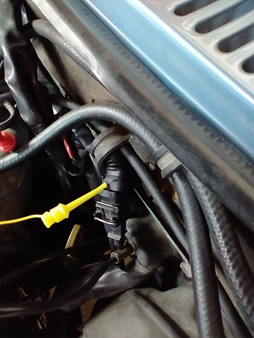
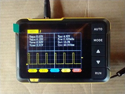
- Crankshaft Position Sensor (CPS): A CPS waveform is used to determine the position and speed of the crankshaft. The waveform typically consists of a series of pulses, with variations in amplitude and frequency indicating potential issues.
- Camshaft Position Sensor (CMP): A CMP waveform is used to determine the position of the camshaft. The waveform is similar to a CPS waveform, with pulses indicating the camshaft’s position.
- Fuel Injector: A fuel injector waveform shows the electrical signal that controls the opening and closing of the fuel injector. The waveform consists of a pulse that indicates when the injector is open and fuel is being injected.
- Ignition Coil Primary: The ignition coil primary waveform shows the voltage and current in the primary circuit of the ignition coil. The waveform consists of a series of pulses, with variations in amplitude and duration indicating potential issues.
- Oxygen Sensor (O2 Sensor): The oxygen sensor waveform shows the voltage output of the oxygen sensor, which indicates the air-fuel ratio in the exhaust gas. The waveform typically oscillates between 0.1V and 0.9V.
- Manifold Absolute Pressure (MAP) Sensor: The MAP sensor waveform shows the voltage output of the MAP sensor, which indicates the pressure in the intake manifold. The waveform varies with engine load and RPM.
- Throttle Position Sensor (TPS): The throttle position sensor waveform shows the voltage output of the TPS, which indicates the position of the throttle plate. The waveform varies with throttle position.
- Air Flow Meter (AFM): The air flow meter waveform shows the voltage output of the AFM, which indicates the amount of air flowing into the engine. The waveform varies with engine load and RPM.
- CAN Bus: A CAN bus waveform shows the data signals being transmitted on the CAN bus network. The waveform consists of a series of pulses, with variations in amplitude and duration indicating potential communication issues.
 Power-Stage-idle.jpg
11. What Are Some Common Mistakes to Avoid When Using an Oscilloscope?
Common mistakes to avoid when using an oscilloscope include incorrect probe placement, improper grounding, and misinterpreting waveforms, all of which can lead to inaccurate diagnoses. Avoiding common mistakes is crucial for accurate and effective car diagnostics. Here are some common mistakes to avoid when using an oscilloscope:
- Incorrect Probe Placement: Ensure that you are connecting the probe to the correct test point in the circuit.
- Improper Grounding: Make sure that the ground clip of the probe is connected to a known good ground point on the vehicle.
- Incorrect Voltage Scale: Set the voltage scale to an appropriate level to display the signal at a reasonable size on the screen.
- Incorrect Time Base: Set the time base to an appropriate level to display the signal over a suitable time period.
- Improper Triggering: Configure the triggering to stabilize the waveform and capture the events of interest.
- Misinterpreting Waveforms: Analyze the waveforms carefully and compare them to known good waveforms to identify anomalies and potential faults.
- Ignoring Noise: Be aware of noise in the signal and take steps to minimize it, such as using shielded cables and proper grounding techniques.
- Overlooking Intermittent Problems: Capture transient events and intermittent faults by using appropriate triggering and memory depth settings.
- Neglecting Documentation: Refer to vehicle-specific wiring diagrams and technical information to ensure accurate testing and diagnosis.
- Forgetting to Calibrate: Always calibrate your oscilloscope before use to ensure accurate measurements.
12. How Can You Improve Your Oscilloscope Car Diagnostics Skills?
You can improve your oscilloscope car diagnostics skills through continuous learning, hands-on practice, and utilizing resources like CAR-TOOL.EDU.VN to stay updated on the latest techniques and technologies. Improving your skills in oscilloscope car diagnostics requires a combination of education, practice, and continuous learning. Here are some tips to help you enhance your abilities:
- Take Training Courses: Enroll in automotive oscilloscope training courses to learn the fundamentals of waveform analysis and diagnostic techniques.
- Practice Regularly: Use the oscilloscope on a variety of vehicles and systems to gain hands-on experience.
- Study Waveform Examples: Review waveform examples from known good and faulty systems to learn how to identify common anomalies.
- Join Online Forums: Participate in online forums and communities to exchange knowledge and learn from other technicians.
- Read Technical Articles: Stay updated on the latest diagnostic techniques and technologies by reading technical articles and publications.
- Attend Industry Events: Attend industry events and trade shows to network with other professionals and learn about new products and services.
- Use Simulation Software: Use oscilloscope simulation software to practice analyzing waveforms and diagnosing faults in a virtual environment.
- Get Mentorship: Seek guidance from experienced technicians who are proficient in oscilloscope diagnostics.
- Document Your Findings: Keep a log of your diagnostic findings, including waveforms, test results, and repair procedures, to build a reference library for future use.
- Continuously Learn: Stay curious and committed to continuous learning to keep up with the rapidly evolving automotive technology.
13. What Are the Safety Precautions to Take When Using an Oscilloscope?
Safety precautions to take when using an oscilloscope include wearing appropriate personal protective equipment (PPE), ensuring proper grounding, and being aware of high-voltage components to prevent injury. When using an oscilloscope for car diagnostics, safety should always be a top priority. Here are some essential safety precautions to follow:
- Wear Personal Protective Equipment (PPE): Always wear safety glasses, gloves, and appropriate clothing to protect yourself from electrical hazards and potential injuries.
- Ensure Proper Grounding: Connect the ground clip of the probe to a known good ground point on the vehicle to prevent ground loops and electrical shock.
- Be Aware of High-Voltage Components: Exercise caution when working around high-voltage components, such as ignition coils and spark plugs.
- Use Insulated Tools: Use insulated tools to prevent electrical shock when working on live circuits.
- Disconnect the Battery: Disconnect the vehicle’s battery before performing any major electrical repairs or diagnostics to prevent accidental shorts and electrical fires.
- Follow Vehicle-Specific Procedures: Refer to vehicle-specific wiring diagrams and technical information to ensure safe testing and diagnosis.
- Keep the Work Area Clean: Keep the work area clean and free of clutter to prevent accidents and injuries.
- Avoid Working Alone: Whenever possible, work with a partner to provide assistance and support in case of an emergency.
- Inspect Equipment Regularly: Inspect the oscilloscope, probes, and cables regularly for damage or wear and tear. Replace any damaged equipment immediately.
- Follow Manufacturer’s Instructions: Always follow the manufacturer’s instructions for the safe operation of the oscilloscope and related equipment.
14. How Does Oscilloscope Car Diagnostics Help with Intermittent Issues?
Oscilloscope car diagnostics helps with intermittent issues by capturing transient events and anomalies that traditional diagnostic tools may miss, providing a detailed view of the electrical signals over time. Automotive expert Bernie Thompson notes that “an oscilloscope is indispensable for diagnosing intermittent problems because it can capture the events leading up to the fault, giving you a clear picture of what’s happening.”
- Capture Transient Events: Oscilloscopes can capture brief, fleeting events that are difficult to detect with other methods.
- Monitor Signals Over Time: By continuously monitoring electrical signals, oscilloscopes can identify patterns and anomalies that occur intermittently.
- Use Triggering Effectively: Advanced triggering options, such as pulse width triggering and window triggering, can be used to capture specific events of interest.
- Analyze Waveform History: Some oscilloscopes have the ability to record and play back waveform history, allowing you to review past events and identify intermittent faults.
- Isolate the Root Cause: By analyzing the waveforms captured during an intermittent event, you can pinpoint the root cause of the problem and recommend appropriate repairs.
15. What Training Resources Are Available for Learning Oscilloscope Diagnostics?
Training resources available for learning oscilloscope diagnostics include online courses, hands-on workshops, and comprehensive guides offered by institutions like CAR-TOOL.EDU.VN. Several resources are available to help you learn oscilloscope diagnostics and improve your skills:
- Online Courses: Many online platforms offer courses on automotive oscilloscope diagnostics, covering topics such as waveform analysis, probe techniques, and diagnostic strategies.
- Hands-On Workshops: Hands-on workshops provide practical experience using oscilloscopes on real vehicles, allowing you to apply what you’ve learned in a controlled environment.
- Technical Books: Several technical books cover automotive oscilloscope diagnostics, providing detailed explanations of waveform analysis and diagnostic techniques.
- Online Forums: Online forums and communities provide a platform for exchanging knowledge and learning from other technicians.
- Video Tutorials: Video tutorials demonstrate how to use oscilloscopes for various diagnostic tasks, providing visual guidance and step-by-step instructions.
- Manufacturer Training: Some oscilloscope manufacturers offer training courses and resources to help you learn how to use their products effectively.
- ASE Certification: The National Institute for Automotive Service Excellence (ASE) offers certification programs for automotive technicians, including a certification in electrical/electronic systems that covers oscilloscope diagnostics.
- Community Colleges and Technical Schools: Many community colleges and technical schools offer automotive technology programs that include training in oscilloscope diagnostics.
- Mentorship Programs: Mentorship programs pair experienced technicians with novice technicians to provide guidance and support in learning oscilloscope diagnostics.
- CAR-TOOL.EDU.VN: CAR-TOOL.EDU.VN offers comprehensive resources, including articles, guides, and training materials, to help you master oscilloscope diagnostics.
16. How Do You Interpret a Crankshaft Position Sensor (CPS) Waveform?
Interpreting a Crankshaft Position Sensor (CPS) waveform involves analyzing the signal’s amplitude, frequency, and pattern to identify issues such as signal loss, distortion, or incorrect timing. The CPS waveform is a crucial diagnostic tool for assessing engine performance and identifying potential issues. Here’s how to interpret a CPS waveform:
- Amplitude: The amplitude of the CPS waveform represents the voltage level of the signal. A healthy CPS waveform should have a consistent amplitude that meets the manufacturer’s specifications.
- Frequency: The frequency of the CPS waveform is proportional to the engine RPM. As the engine RPM increases, the frequency of the waveform also increases.
- Pattern: The CPS waveform typically consists of a series of pulses, with variations in amplitude and duration indicating the position of the crankshaft. The pattern should be consistent and regular.
- Missing Pulses: Missing pulses in the CPS waveform can indicate a faulty sensor, damaged flywheel/flexplate, or wiring issues.
- Distorted Waveform: A distorted CPS waveform can indicate a faulty sensor, electromagnetic interference, or wiring issues.
- Incorrect Timing: Incorrect timing of the CPS waveform can indicate a misaligned sensor, damaged flywheel/flexplate, or timing belt/chain issues.
- Compare to Known Good Waveform: Compare the CPS waveform to a known good waveform for the same vehicle and engine to identify any anomalies.
- Use a Scope Meter: Use a scope meter or oscilloscope to capture and analyze the CPS waveform accurately.
- Check for DTCs: Check for diagnostic trouble codes (DTCs) related to the CPS to help narrow down the potential causes of the issue.
- Perform Further Testing: Perform further testing, such as resistance and voltage tests, to verify the condition of the CPS and related components.
17. What Is the Role of Triggering in Oscilloscope Car Diagnostics?
Triggering in oscilloscope car diagnostics plays a crucial role in stabilizing waveforms, allowing technicians to capture and analyze specific events or signals for accurate diagnosis. Triggering is essential for capturing stable and repeatable waveforms on an oscilloscope. It allows you to synchronize the oscilloscope’s display with a specific event in the signal, making it easier to analyze the waveform. Here’s the role of triggering in oscilloscope car diagnostics:
- Stabilize Waveforms: Triggering stabilizes the waveform on the screen, preventing it from drifting or flickering.
- Capture Specific Events: Triggering allows you to capture specific events in the signal, such as the start of a pulse or the occurrence of a fault.
- Synchronize Display: Triggering synchronizes the oscilloscope’s display with the signal, ensuring that the waveform is displayed consistently each time.
- Types of Triggering: Common triggering options include:
- Auto: Automatically triggers the waveform.
- Normal: Triggers the waveform only when the signal crosses a specified threshold.
- Single: Captures a single waveform when the trigger condition is met.
- Trigger Source: The trigger source is the channel that is used to trigger the oscilloscope.
- Trigger Level: The trigger level is the voltage level at which the oscilloscope triggers.
- Trigger Slope: The trigger slope is the direction in which the signal must cross the trigger level to trigger the oscilloscope.
- Trigger Mode: The trigger mode determines how the oscilloscope triggers.
- Use Advanced Triggering: Use advanced triggering options, such as pulse width triggering and window triggering, to capture specific events of interest.
- Adjust Trigger Settings: Adjust the trigger settings carefully to capture the desired waveform and stabilize the display.
18. How Do You Use a Current Clamp with an Oscilloscope for Car Diagnostics?
Using a current clamp with an oscilloscope for car diagnostics involves clamping the probe around a wire to measure current flow without breaking the circuit, allowing for non-intrusive analysis of electrical signals. A current clamp is a valuable tool for measuring current flow in a circuit without breaking the connection. It works by clamping around a wire and measuring the magnetic field generated by the current. Here’s how to use a current clamp with an oscilloscope for car diagnostics:
- Select the Appropriate Current Clamp: Choose a current clamp that is suitable for the expected current range of the circuit you are testing.
- Connect the Current Clamp to the Oscilloscope: Connect the current clamp to the oscilloscope using a BNC cable.
- Zero the Current Clamp: Zero the current clamp according to the manufacturer’s instructions to eliminate any offset.
- Clamp the Current Clamp Around the Wire: Clamp the current clamp around the wire you want to measure. Make sure that the clamp is fully closed and that the wire is centered in the clamp.
- Set the Oscilloscope Settings: Set the oscilloscope settings to display the current waveform. Adjust the voltage scale and time base as needed to get a clear and stable display.
- Observe the Waveform: Observe the current waveform on the screen and analyze it to identify any anomalies or issues.
- Use the Correct Polarity: Pay attention to the polarity of the current clamp. Some current clamps have a polarity switch that allows you to reverse the polarity of the output signal.
- Avoid Overloading the Current Clamp: Do not exceed the maximum current rating of the current clamp.
- Use Shielded Cables: Use shielded cables to minimize noise and interference in the current signal.
- Calibrate Regularly: Calibrate the current clamp regularly to ensure accurate measurements.
19. What Are the Benefits of Using Automotive Waveform Libraries?
Using automotive waveform libraries provides technicians with reference signals for comparison, reducing diagnostic time and improving accuracy by identifying deviations from known good waveforms. Automotive waveform libraries are collections of known good waveforms from various vehicle systems and components. They provide a valuable reference for technicians when diagnosing electrical issues. Here are the benefits of using automotive waveform libraries:
- Reference Signals: Waveform libraries provide reference signals for comparison, allowing technicians to quickly identify deviations from known good waveforms.
- Reduced Diagnostic Time: By comparing waveforms to known good examples, technicians can reduce diagnostic time and pinpoint the source of the problem faster.
- Improved Accuracy: Waveform libraries improve diagnostic accuracy by providing a reliable reference for evaluating electrical signals.
- Comprehensive Coverage: Many waveform libraries cover a wide range of vehicles and systems, providing comprehensive diagnostic support.
- Easy Access: Waveform libraries are often available online or as part of oscilloscope software, making them easily accessible to technicians.
- Expert Knowledge: Waveform libraries are created by experienced technicians and engineers, providing access to expert knowledge and insights.
- Continuous Updates: Waveform libraries are continuously updated with new waveforms and diagnostic information, ensuring that technicians have access to the latest data.
- Training Resources: Waveform libraries can be used as training resources to help technicians learn how to analyze waveforms and diagnose electrical issues.
- Cost Savings: By reducing diagnostic time and improving accuracy, waveform libraries can help technicians save time and money on repairs.
- Enhanced Customer Satisfaction: By providing accurate and efficient diagnostics, waveform libraries can help technicians enhance customer satisfaction and build trust.
20. What Are the Latest Trends in Oscilloscope Car Diagnostics?
Latest trends in oscilloscope car diagnostics include the integration of AI-powered diagnostics, cloud-based waveform libraries, and enhanced wireless connectivity for remote analysis. Keeping up with the latest trends in oscilloscope car diagnostics is essential for staying competitive and providing the best possible service to your customers. Here are some of the latest trends in oscilloscope car diagnostics:
- AI-Powered Diagnostics: Artificial intelligence (AI) is being integrated into oscilloscopes to automate waveform analysis and provide diagnostic suggestions.
- Cloud-Based Waveform Libraries: Cloud-based waveform libraries provide access to a vast collection of known good waveforms from various vehicles and systems.
- Enhanced Wireless Connectivity: Enhanced wireless connectivity allows technicians to remotely access oscilloscopes and share data with other technicians or experts.
- Improved User Interfaces: Oscilloscopes are being designed with more intuitive user interfaces to make them easier to use and more efficient for diagnostics.
- Integration with Scan Tools: Oscilloscopes are being integrated with scan tools to provide a comprehensive diagnostic solution that combines code reading with waveform analysis.
- Increased Bandwidth and Sampling Rate: Oscilloscopes are being developed with higher bandwidth and sampling rates to capture faster and more complex signals.
- Advanced Triggering Options: Advanced triggering options, such as pulse width triggering and window triggering, are becoming more common on oscilloscopes.
- Portable and Rugged Designs: Oscilloscopes are being designed to be more portable and rugged, making them suitable for use in a variety of environments.
- Subscription-Based Services: Some oscilloscope manufacturers are offering subscription-based services that provide access to software updates, waveform libraries, and technical support.
- Training and Certification Programs: Training and certification programs are being developed to help technicians learn how to use oscilloscopes effectively and stay up-to-date with the latest diagnostic techniques.
By staying informed about these trends and investing in the latest technology and training, you can enhance your diagnostic capabilities and provide your customers with the best possible service.
FAQ: Oscilloscope Car Diagnostics
Q1: What type of oscilloscope is best for automotive diagnostics?
The best type of oscilloscope for automotive diagnostics is a digital storage oscilloscope (DSO) with a bandwidth of at least 100 MHz, a sampling rate of at least 500 MS/s, and a memory depth of at least 10,000 points. A digital storage oscilloscope (DSO) is generally considered the best type for automotive diagnostics due to its ability to capture, store, and display waveforms with high precision.
Q2: How do I connect an oscilloscope to a car?
To connect an oscilloscope to a car, use appropriate probes (voltage, current, or ignition), connect the ground clip to a known good ground, and attach the probe tip to the test point in the circuit you want to measure. First, identify the test points in the vehicle’s electrical system that you want to analyze.
Q3: What is a good bandwidth for an automotive oscilloscope?
A good bandwidth for an automotive oscilloscope is at least 100 MHz to accurately capture the fast-changing signals in modern vehicle electronics. A higher bandwidth ensures that you can accurately measure high-frequency signals without attenuation or distortion.
Q4: What is the difference between a 1x and 10x oscilloscope probe?
A 1x probe provides a direct signal with no attenuation, while a 10x probe attenuates the signal by a factor of 10, allowing measurement of higher voltages and reducing circuit loading. Using a 10x probe also reduces the effect of the probe’s capacitance on the circuit, which can improve accuracy.
Q5: How do I trigger an oscilloscope for car diagnostics?
To trigger an oscilloscope, select the appropriate trigger source (channel), set the trigger level to a suitable voltage, and choose the trigger mode (auto, normal, or single) to stabilize the waveform. Adjusting the trigger settings allows you to capture and display the waveform at the desired point.
Q6: What is a CAN bus waveform and how do I read it?
A CAN bus waveform is a series of pulses representing data transmitted on the vehicle’s communication network. It can be read by analyzing the voltage levels and timing of the pulses to identify communication issues. Proper analysis requires an oscilloscope with CAN bus decoding capabilities.
Q7: How do I use a current clamp with an oscilloscope?
To use a current clamp, connect it to the oscilloscope, zero the clamp, clamp it around the wire you want to measure, and set the oscilloscope settings to display the current waveform. Ensure the clamp is properly aligned and calibrated for accurate readings.
Q8: What are common mistakes to avoid when using an oscilloscope for car diagnostics?
Common mistakes include incorrect probe placement, improper grounding, incorrect voltage scale, improper triggering, and misinterpreting waveforms. Avoiding these mistakes ensures accurate and reliable diagnostic results.
Q9: What is the role of a crankshaft position sensor (CPS) waveform in diagnostics?
The crankshaft position sensor (CPS) waveform provides information about the position and speed of the crankshaft, which is crucial for diagnosing engine timing and misfire issues. A faulty CPS can cause a no-start condition or poor engine performance.
Q10: How can CAR-TOOL.EDU.VN help me improve my oscilloscope car diagnostic skills?
CAR-TOOL.EDU.VN can help you improve your oscilloscope car diagnostic skills by providing comprehensive resources, including articles, guides, training materials, and access to expert advice. Our platform is designed to support technicians at all skill levels, from beginners to advanced diagnosticians.
Ready to take your automotive diagnostics to the next level? Contact CAR-TOOL.EDU.VN today for expert advice and support on selecting the right tools and techniques for your needs. Visit our website at CAR-TOOL.EDU.VN or reach out via WhatsApp at +1 (641) 206-8880. Our address is 456 Elm Street, Dallas, TX 75201, United States. Don’t miss out on the opportunity to enhance your skills and improve your shop’s efficiency.