Diagnostic Trouble Code (DTC) charts are indispensable tools for pinpointing automotive issues, and CAR-TOOL.EDU.VN provides comprehensive resources to help you understand and resolve them, including providing access to detailed charts for all diagnostic codes for cars and their corresponding fixes. By leveraging these charts, you can efficiently diagnose problems, make informed decisions about repairs, and save time and money. Explore automotive diagnostic codes, OBD-II code definitions, and troubleshooting resources.
Contents
- 1. Decoding Diagnostic Trouble Codes (DTCs)
- 1.1. Standardized vs. Manufacturer-Specific Codes
- 1.2. Using DTC Charts for Accurate Diagnosis
- 1.3. Common Mistakes to Avoid
- 2. Comprehensive OBD-II Trouble Code Chart
- 2.1. Powertrain Codes (P0000 – P0999)
- 2.2. Body Codes (B0000 – B0999)
- 2.3. Chassis Codes (C0000 – C0999)
- 2.4. Network Communication Codes (U0000 – U0999)
- 3. Tools and Equipment for Diagnosing DTCs
- 3.1. Selecting the Right OBD-II Scanner
- 3.2. Advanced Diagnostic Tools
- 3.3. Where to Buy Diagnostic Tools
- 4. Step-by-Step Guide to Diagnosing and Repairing DTCs
- 4.1. Diagnosing Misfire Codes (P0300 – P0308)
- 4.2. Diagnosing Oxygen Sensor Codes (P0131 – P0161)
- 4.3. Diagnosing Evaporative Emission Control System Codes (P0440 – P0457)
- 5. Advanced Diagnostic Techniques
- 5.1. Understanding Freeze Frame Data
- 5.2. Using Technical Service Bulletins (TSBs)
- 5.3. Seeking Professional Help
- 6. Preventive Maintenance to Reduce DTCs
- 6.1. Maintaining the Engine Cooling System
- 6.2. Caring for the Fuel System
- 6.3. Keeping the Electrical System in Good Condition
- 7. Common Myths About Diagnostic Trouble Codes
- 8. The Future of Automotive Diagnostics
1. Decoding Diagnostic Trouble Codes (DTCs)
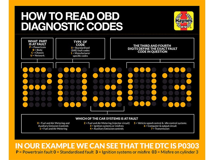
Diagnostic Trouble Codes (DTCs) are alphanumeric codes generated by a vehicle’s On-Board Diagnostics (OBD) system to indicate malfunctions or issues detected within various systems. Understanding the structure and meaning of these codes is crucial for effective automotive diagnostics and repairs. These codes follow a standardized format, making it easier to identify the area and nature of the problem. Here’s a breakdown of how DTCs are structured:
- First Character: Indicates the system where the fault occurred:
- P: Powertrain (engine, transmission, fuel system)
- B: Body (interior, airbags, comfort features)
- C: Chassis (brakes, suspension, steering)
- U: Network Communication (communication between control units)
- Second Character: Specifies whether the code is generic or manufacturer-specific:
- 0: Generic OBD-II code (SAE standard)
- 1: Manufacturer-specific code
- Third Character: Identifies the subsystem related to the fault:
- 0: Fuel and air metering, auxiliary emission controls
- 1: Fuel and air metering
- 2: Fuel and air metering (injector circuit)
- 3: Ignition systems or misfires
- 4: Auxiliary emission controls
- 5: Vehicle speed control & idle control systems
- 6: Computer & output circuit
- 7: Transmission
- Fourth and Fifth Characters: Provide specific information about the nature of the fault. These numbers help to pinpoint the exact issue within the identified system.
 Diagnostic Trouble Codes
1.1. Standardized vs. Manufacturer-Specific Codes
- Standardized (Generic) Codes: These codes are defined by the Society of Automotive Engineers (SAE) and are common across all OBD-II compliant vehicles. They cover basic issues related to emissions, engine performance, and other critical systems.
- Manufacturer-Specific Codes: These codes are defined by the vehicle manufacturer and provide more detailed information about specific issues unique to that make and model. They can cover a wider range of systems and components.
1.2. Using DTC Charts for Accurate Diagnosis
DTC charts are essential tools for technicians and DIY mechanics. These charts list DTCs along with their descriptions and possible causes, providing a starting point for diagnosing automotive issues. CAR-TOOL.EDU.VN offers a comprehensive chart for all diagnostic codes for cars, ensuring you have the resources needed for accurate diagnosis.
Here’s how to use DTC charts effectively:
- Retrieve the DTC: Use an OBD-II scanner to read the DTC from the vehicle’s computer.
- Consult the DTC Chart: Look up the DTC in a reliable chart, such as the one provided by CAR-TOOL.EDU.VN.
- Understand the Code Description: Read the description of the code to understand the potential issue.
- Investigate Possible Causes: Review the list of possible causes associated with the code.
- Perform Diagnostic Tests: Conduct diagnostic tests to confirm the cause of the problem before performing any repairs.
1.3. Common Mistakes to Avoid
- Ignoring Additional Symptoms: DTCs provide a starting point, but it’s crucial to consider other symptoms the vehicle may be exhibiting.
- Replacing Parts Without Proper Diagnosis: Avoid simply replacing parts based on the DTC alone. Perform thorough diagnostic tests to confirm the issue.
- Using Unreliable DTC Charts: Ensure the DTC chart you are using is accurate and up-to-date. CAR-TOOL.EDU.VN provides reliable and comprehensive resources.
2. Comprehensive OBD-II Trouble Code Chart
The following chart provides a detailed overview of common OBD-II trouble codes, their descriptions, and potential causes. Keep in mind that this is not an exhaustive list, and some codes may have variations depending on the vehicle make and model.
| Code | Code Identification | Potential Causes |
|---|---|---|
| P0101 | Mass air flow (MAF) sensor circuit, range or performance problem | Dirty or faulty MAF sensor, intake leaks, wiring issues, PCM failure |
| P0102 | Mass air flow (MAF) sensor circuit, low input | Faulty MAF sensor, wiring issues, vacuum leaks |
| P0103 | Mass air flow (MAF) sensor circuit, high input | Faulty MAF sensor, wiring issues, PCM failure |
| P0106 | Manifold absolute pressure (MAP) sensor circuit, range or performance problem | Faulty MAP sensor, vacuum leaks, wiring issues, PCM failure |
| P0107 | Manifold absolute pressure (MAP) sensor circuit, low input | Faulty MAP sensor, vacuum leaks, wiring issues |
| P0108 | Manifold absolute pressure (MAP) sensor circuit, high input | Faulty MAP sensor, wiring issues, PCM failure |
| P0112 | Intake air temperature (IAT) circuit, low input | Faulty IAT sensor, wiring issues |
| P0113 | Intake air temperature (IAT) circuit, high input | Faulty IAT sensor, wiring issues, PCM failure |
| P0117 | Engine coolant temperature (ECT) circuit, low input | Faulty ECT sensor, wiring issues, low coolant level |
| P0118 | Engine coolant temperature (ECT) circuit, high input | Faulty ECT sensor, wiring issues, PCM failure |
| P0121 | Throttle position sensor (TPS) circuit, range or performance problem | Faulty TPS, wiring issues, throttle body issues |
| P0122 | Throttle position sensor (TPS) circuit, low input | Faulty TPS, wiring issues |
| P0123 | Throttle position sensor (TPS) circuit, high input | Faulty TPS, wiring issues, PCM failure |
| P0125 | Insufficient coolant temperature for closed loop fuel control | Faulty ECT sensor, thermostat issues, cooling system problems |
| P0131 | Oxygen sensor circuit, low voltage (pre-converter sensor, left bank) | Faulty O2 sensor, exhaust leaks, wiring issues |
| P0132 | Oxygen sensor circuit, high voltage (pre-converter sensor, left bank) | Faulty O2 sensor, wiring issues, fuel system issues |
| P0133 | Oxygen sensor circuit, slow response (pre-converter sensor, left bank) | Faulty O2 sensor, exhaust leaks, wiring issues |
| P0134 | Oxygen sensor circuit – no activity detected (pre-converter sensor, left bank) | Faulty O2 sensor, wiring issues, exhaust leaks |
| P0135 | Oxygen sensor heater circuit malfunction (pre-converter sensor, left bank) | Faulty O2 sensor, wiring issues, fuse problems |
| P0137 | Oxygen sensor circuit, low voltage (post-converter sensor, left bank) | Faulty O2 sensor, exhaust leaks, wiring issues |
| P0138 | Oxygen sensor circuit, high voltage (post-converter sensor, left bank) | Faulty O2 sensor, wiring issues, fuel system issues |
| P0140 | Oxygen sensor circuit – no activity detected (post-converter sensor, left bank) | Faulty O2 sensor, wiring issues, exhaust leaks |
| P0141 | Oxygen sensor heater circuit malfunction (post-converter sensor, left bank) | Faulty O2 sensor, wiring issues, fuse problems |
| P0143 | Oxygen sensor circuit, low voltage (#2 post-converter sensor, left bank) | Faulty O2 sensor, exhaust leaks, wiring issues |
| P0144 | Oxygen sensor circuit, high voltage (#2 post-converter sensor, left bank) | Faulty O2 sensor, wiring issues, fuel system issues |
| P0146 | Oxygen sensor circuit – no activity detected (#2 post-converter sensor, left bank) | Faulty O2 sensor, wiring issues, exhaust leaks |
| P0147 | Oxygen sensor heater circuit malfunction (#2 post-converter sensor, left bank) | Faulty O2 sensor, wiring issues, fuse problems |
| P0151 | Oxygen sensor circuit, low voltage (pre-converter sensor, right bank) | Faulty O2 sensor, exhaust leaks, wiring issues |
| P0152 | Oxygen sensor circuit, high voltage (pre-converter sensor, right bank) | Faulty O2 sensor, wiring issues, fuel system issues |
| P0153 | Oxygen sensor circuit, slow response (pre-converter sensor, right bank) | Faulty O2 sensor, exhaust leaks, wiring issues |
| P0154 | Oxygen sensor circuit – no activity detected (pre-converter sensor, right bank) | Faulty O2 sensor, wiring issues, exhaust leaks |
| P0155 | Oxygen sensor heater circuit malfunction (pre-converter sensor, right bank) | Faulty O2 sensor, wiring issues, fuse problems |
| P0157 | Oxygen sensor circuit, low voltage (post-converter sensor, right bank) | Faulty O2 sensor, exhaust leaks, wiring issues |
| P0158 | Oxygen sensor circuit, high voltage (post-converter sensor, right bank) | Faulty O2 sensor, wiring issues, fuel system issues |
| P0160 | Oxygen sensor circuit – no activity detected (post-converter sensor, right bank) | Faulty O2 sensor, wiring issues, exhaust leaks |
| P0161 | Oxygen sensor heater circuit malfunction (post-converter sensor, right bank) | Faulty O2 sensor, wiring issues, fuse problems |
| P0171 | System too lean, left bank | Vacuum leaks, faulty MAF sensor, fuel system issues, faulty O2 sensor |
| P0172 | System too rich, left bank | Faulty O2 sensor, fuel system issues, faulty MAF sensor |
| P0174 | System too lean, right bank | Vacuum leaks, faulty MAF sensor, fuel system issues, faulty O2 sensor |
| P0175 | System too rich, right bank | Faulty O2 sensor, fuel system issues, faulty MAF sensor |
| P0300 | Engine misfire detected | Ignition system issues, fuel system issues, vacuum leaks, low compression |
| P0301 | Cylinder number 1 misfire detected | Ignition system issues, fuel system issues, vacuum leaks, low compression in cylinder 1 |
| P0302 | Cylinder number 2 misfire detected | Ignition system issues, fuel system issues, vacuum leaks, low compression in cylinder 2 |
| P0303 | Cylinder number 3 misfire detected | Ignition system issues, fuel system issues, vacuum leaks, low compression in cylinder 3 |
| P0304 | Cylinder number 4 misfire detected | Ignition system issues, fuel system issues, vacuum leaks, low compression in cylinder 4 |
| P0305 | Cylinder number 5 misfire detected | Ignition system issues, fuel system issues, vacuum leaks, low compression in cylinder 5 |
| P0306 | Cylinder number 6 misfire detected | Ignition system issues, fuel system issues, vacuum leaks, low compression in cylinder 6 |
| P0307 | Cylinder number 7 misfire detected | Ignition system issues, fuel system issues, vacuum leaks, low compression in cylinder 7 |
| P0308 | Cylinder number 8 misfire detected | Ignition system issues, fuel system issues, vacuum leaks, low compression in cylinder 8 |
| P0325 | Knock sensor circuit malfunction | Faulty knock sensor, wiring issues, PCM failure |
| P0327 | Knock sensor circuit, low output | Faulty knock sensor, wiring issues |
| P0336 | Crankshaft position sensor circuit, range or performance problem | Faulty crankshaft sensor, wiring issues, timing issues |
| P0337 | Crankshaft position sensor, low output | Faulty crankshaft sensor, wiring issues |
| P0338 | Crankshaft position sensor, high output | Faulty crankshaft sensor, wiring issues, PCM failure |
| P0339 | Crankshaft position sensor, circuit intermittent | Faulty crankshaft sensor, wiring issues |
| P0340 | Camshaft position sensor circuit | Faulty camshaft sensor, wiring issues, timing issues |
| P0341 | Camshaft position sensor circuit, range or performance problem | Faulty camshaft sensor, wiring issues, timing issues |
| P0401 | Exhaust gas recirculation, insufficient flow detected | Faulty EGR valve, clogged EGR passages, vacuum leaks |
| P0404 | Exhaust gas recirculation circuit, range or performance problem | Faulty EGR valve, wiring issues, PCM failure |
| P0405 | Exhaust gas recirculation sensor circuit low | Faulty EGR sensor, wiring issues |
| P0410 | Secondary air injection system | Faulty air pump, vacuum leaks, check valve issues |
| P0418 | Secondary air injection pump relay control circuit | Faulty air pump relay, wiring issues, PCM failure |
| P0420 | Catalyst system efficiency below threshold, left bank | Faulty catalytic converter, exhaust leaks, faulty O2 sensors |
| P0430 | Catalyst system efficiency below threshold, right bank | Faulty catalytic converter, exhaust leaks, faulty O2 sensors |
| P0440 | Evaporative emission control system malfunction | Vacuum leaks, faulty gas cap, faulty purge valve |
| P0441 | Evaporative emission control system, purge control circuit malfunction | Faulty purge valve, wiring issues, vacuum leaks |
| P0442 | Evaporative emission control system, small leak detected | Vacuum leaks, faulty gas cap, faulty purge valve |
| P0446 | Evaporative emission control system, vent system performance | Faulty vent valve, clogged vent line, wiring issues |
| P0452 | Evaporative emission control system, pressure sensor low input | Faulty pressure sensor, wiring issues |
| P0453 | Evaporative emission control system, pressure sensor high input | Faulty pressure sensor, wiring issues, PCM failure |
| P0461 | Fuel level sensor circuit, range or performance problem | Faulty fuel level sensor, wiring issues |
| P0462 | Fuel level sensor circuit, low input | Faulty fuel level sensor, wiring issues |
| P0463 | Fuel level sensor circuit, high input | Faulty fuel level sensor, wiring issues, PCM failure |
| P0500 | Vehicle speed sensor circuit | Faulty speed sensor, wiring issues, PCM failure |
| P0506 | Idle control system, rpm lower than expected | Vacuum leaks, faulty idle air control valve, throttle body issues |
| P0507 | Idle control system, rpm higher than expected | Vacuum leaks, faulty idle air control valve, throttle body issues |
| P0601 | Powertrain Control Module, memory error | Faulty PCM, software issues |
| P0602 | Powertrain Control module, programming error | Faulty PCM, software issues |
| P0603 | Powertrain Control Module, memory reset error | Faulty PCM, software issues |
| P0604 | Powertrain Control Module, memory error (RAM) | Faulty PCM, software issues |
| P0605 | Powertrain Control Module, memory error (ROM) | Faulty PCM, software issues |
Not all codes apply to all models
2.1. Powertrain Codes (P0000 – P0999)
Powertrain codes relate to the engine, transmission, and related components. These are among the most common codes encountered.
- P0101 – Mass Air Flow (MAF) Sensor Circuit Range/Performance: Indicates an issue with the MAF sensor, which measures the amount of air entering the engine. According to a study by the University of California, Berkeley, faulty MAF sensors can lead to decreased fuel efficiency and poor engine performance.
- P0300 – Random/Multiple Cylinder Misfire Detected: Signals that the engine is misfiring, which can be due to various issues such as faulty spark plugs, ignition coils, or fuel injectors. Research from the Argonne National Laboratory highlights that misfires can significantly increase emissions and reduce engine lifespan.
- P0420 – Catalyst System Efficiency Below Threshold (Bank 1): Points to a problem with the catalytic converter’s ability to reduce emissions. A report by the EPA indicates that a failing catalytic converter can lead to increased pollution and potential vehicle failure during emissions testing.
2.2. Body Codes (B0000 – B0999)
Body codes pertain to components within the vehicle’s body, such as airbags, power windows, and security systems.
- B0001 – Driver Frontal Airbag Deployment Control: Indicates a problem with the driver’s side airbag system.
- B0002 – Passenger Frontal Airbag Deployment Control: Indicates a problem with the passenger’s side airbag system.
2.3. Chassis Codes (C0000 – C0999)
Chassis codes relate to systems such as ABS (Anti-lock Braking System), traction control, and suspension.
- C0035 – Front Wheel Speed Sensor Circuit: Signals an issue with the wheel speed sensor, which is crucial for ABS and traction control systems. Studies from the National Highway Traffic Safety Administration (NHTSA) emphasize that faulty wheel speed sensors can compromise vehicle safety.
2.4. Network Communication Codes (U0000 – U0999)
Network communication codes involve issues with the vehicle’s communication network, such as CAN (Controller Area Network) bus.
- U0100 – Lost Communication with ECM/PCM: Indicates a loss of communication between the vehicle’s main computer (ECM/PCM) and other modules.
3. Tools and Equipment for Diagnosing DTCs
Effectively diagnosing DTCs requires the right tools and equipment. Here are some essential items:
- OBD-II Scanner: A handheld device that plugs into the vehicle’s OBD-II port to read DTCs and other diagnostic information.
- Multimeter: Used to test electrical circuits and components for voltage, resistance, and continuity.
- Scan Tool Software: Advanced software that provides more detailed diagnostic information and capabilities than basic OBD-II scanners.
- Vacuum Tester: Helps identify vacuum leaks, which can cause various engine performance issues.
- Fuel Pressure Tester: Used to measure fuel pressure, which is crucial for diagnosing fuel system problems.
- Compression Tester: Measures cylinder compression to identify issues such as worn piston rings or valves.
3.1. Selecting the Right OBD-II Scanner
When choosing an OBD-II scanner, consider the following factors:
- Compatibility: Ensure the scanner is compatible with the make and model of your vehicle.
- Features: Look for features such as live data streaming, freeze frame data, and the ability to clear DTCs.
- Ease of Use: Choose a scanner with a user-friendly interface and clear instructions.
- Price: Balance features and functionality with your budget.
3.2. Advanced Diagnostic Tools
For more complex diagnostic tasks, consider investing in advanced tools such as:
- Professional Scan Tools: These tools offer advanced features such as bidirectional control, component testing, and access to manufacturer-specific data.
- Oscilloscopes: Used to analyze electrical signals and diagnose complex electrical issues.
- Smoke Machines: Help locate vacuum leaks by introducing smoke into the intake system.
3.3. Where to Buy Diagnostic Tools
You can purchase diagnostic tools from various sources, including:
- Auto Parts Stores: Local auto parts stores such as AutoZone and Advance Auto Parts offer a range of OBD-II scanners and other diagnostic tools.
- Online Retailers: Online retailers such as Amazon and eBay offer a wide selection of diagnostic tools at competitive prices.
- Specialty Tool Suppliers: Specialty tool suppliers such as Snap-on and Matco Tools offer high-quality professional-grade diagnostic tools.
4. Step-by-Step Guide to Diagnosing and Repairing DTCs
Diagnosing and repairing DTCs involves a systematic approach to identify the root cause of the problem and implement the appropriate repair. Here’s a step-by-step guide:
- Verify the Problem:
- Confirm the vehicle is exhibiting symptoms or issues.
- Check for any warning lights on the dashboard.
- Retrieve DTCs:
- Connect an OBD-II scanner to the vehicle’s OBD-II port.
- Read and record any DTCs present.
- Research DTCs:
- Consult a reliable DTC chart, such as the one provided by CAR-TOOL.EDU.VN, to understand the meaning and potential causes of the DTCs.
- Gather Additional Information:
- Check for any technical service bulletins (TSBs) related to the DTCs and vehicle make/model.
- Review vehicle repair manuals and online forums for relevant information.
- Inspect the Vehicle:
- Perform a visual inspection of the affected components and systems.
- Check for any obvious signs of damage, wear, or leaks.
- Perform Diagnostic Tests:
- Use diagnostic tools such as multimeters, vacuum testers, and fuel pressure testers to verify the cause of the problem.
- Follow the diagnostic procedures outlined in the vehicle repair manual.
- Repair the Vehicle:
- Replace faulty components as needed.
- Repair any wiring issues or vacuum leaks.
- Verify the Repair:
- Clear the DTCs using the OBD-II scanner.
- Perform a test drive to ensure the problem is resolved and no new issues have emerged.
- Monitor the Vehicle:
- Keep an eye on the vehicle for any recurring symptoms or warning lights.
- Recheck the DTCs periodically to ensure the repair was effective.
4.1. Diagnosing Misfire Codes (P0300 – P0308)
Misfire codes can be challenging to diagnose because they can be caused by a variety of issues. Here’s a systematic approach:
- Check for Obvious Issues:
- Inspect spark plugs, ignition coils, and fuel injectors for damage or wear.
- Check for vacuum leaks around the intake manifold and vacuum lines.
- Perform Compression Test:
- Use a compression tester to measure cylinder compression.
- Low compression can indicate worn piston rings or valves.
- Test Ignition System:
- Use a spark tester to check for spark at each spark plug.
- Test ignition coils using a multimeter to check for proper resistance.
- Test Fuel System:
- Check fuel pressure using a fuel pressure tester.
- Test fuel injectors using a multimeter to check for proper resistance and spray pattern.
4.2. Diagnosing Oxygen Sensor Codes (P0131 – P0161)
Oxygen sensor codes often indicate issues with the O2 sensors themselves, but they can also be caused by other problems:
- Inspect O2 Sensors:
- Check O2 sensors for damage or contamination.
- Check wiring and connectors for corrosion or damage.
- Test O2 Sensor Heater Circuit:
- Use a multimeter to check for proper voltage at the O2 sensor heater circuit.
- Check for Exhaust Leaks:
- Inspect the exhaust system for leaks, especially near the O2 sensors.
- Monitor O2 Sensor Data:
- Use an OBD-II scanner to monitor O2 sensor data in real-time.
- Look for abnormal readings or slow response times.
4.3. Diagnosing Evaporative Emission Control System Codes (P0440 – P0457)
Evaporative emission control system (EVAP) codes can be difficult to diagnose due to the complexity of the system:
- Check Gas Cap:
- Ensure the gas cap is properly tightened and in good condition.
- Inspect EVAP System Hoses:
- Check EVAP system hoses for cracks, leaks, or damage.
- Test Purge Valve:
- Use a scan tool to activate the purge valve and check for proper operation.
- Check the purge valve for leaks using a vacuum tester.
- Test Vent Valve:
- Check the vent valve for proper operation and leaks.
- Perform Smoke Test:
- Use a smoke machine to introduce smoke into the EVAP system and locate leaks.
5. Advanced Diagnostic Techniques
For complex or intermittent issues, advanced diagnostic techniques may be necessary. These techniques require specialized tools and expertise.
- Using a Scan Tool for Live Data:
- Scan tools can display live data from various sensors and systems, allowing technicians to monitor performance in real-time.
- This can help identify issues that may not trigger a DTC but are still affecting vehicle performance.
- Performing Component Testing:
- Component testing involves using diagnostic tools to test individual components and verify their functionality.
- This can help pinpoint faulty components and avoid unnecessary replacements.
- Using an Oscilloscope:
- Oscilloscopes can analyze electrical signals and identify complex electrical issues that may not be detectable with a multimeter.
- This can be particularly useful for diagnosing issues with sensors, actuators, and control modules.
5.1. Understanding Freeze Frame Data
Freeze frame data is a snapshot of sensor data recorded by the vehicle’s computer at the time a DTC is set. This data can provide valuable insights into the conditions that led to the problem.
- Accessing Freeze Frame Data:
- Use an OBD-II scanner to access freeze frame data.
- The data typically includes parameters such as engine speed, engine load, coolant temperature, and fuel trim.
- Interpreting Freeze Frame Data:
- Analyze the freeze frame data to identify any abnormal readings or conditions.
- Compare the data to specifications to determine if any sensors or systems are operating outside of their normal range.
5.2. Using Technical Service Bulletins (TSBs)
Technical Service Bulletins (TSBs) are issued by vehicle manufacturers to provide information about common problems and their solutions.
- Accessing TSBs:
- TSBs can be accessed through online databases or by contacting the vehicle manufacturer.
- Using TSBs for Diagnosis:
- Check for TSBs related to the DTCs and vehicle make/model.
- TSBs may provide valuable diagnostic and repair information.
5.3. Seeking Professional Help
For complex or persistent issues, it may be necessary to seek professional help from a qualified technician.
- Finding a Reputable Technician:
- Look for technicians who are certified by organizations such as ASE (National Institute for Automotive Service Excellence).
- Check online reviews and ask for recommendations from friends and family.
- Communicating with the Technician:
- Provide the technician with all relevant information, including the DTCs, symptoms, and any diagnostic steps you have already taken.
- Ask the technician to explain the diagnosis and repair process.
6. Preventive Maintenance to Reduce DTCs
Preventive maintenance can help reduce the likelihood of DTCs and keep your vehicle running smoothly.
- Regular Oil Changes:
- Follow the manufacturer’s recommended oil change interval.
- Use the correct type of oil for your vehicle.
- Air Filter Replacement:
- Replace the air filter regularly to ensure proper airflow to the engine.
- Spark Plug Replacement:
- Replace spark plugs according to the manufacturer’s recommended interval.
- Fluid Checks:
- Check and top off fluids such as coolant, brake fluid, power steering fluid, and transmission fluid.
- Tire Maintenance:
- Maintain proper tire pressure and rotate tires regularly.
- Brake Inspection:
- Inspect brakes regularly for wear and damage.
- Battery Maintenance:
- Keep battery terminals clean and check battery voltage.
6.1. Maintaining the Engine Cooling System
The engine cooling system is critical for preventing overheating and engine damage.
- Coolant Flush:
- Flush the cooling system every two to three years to remove contaminants and prevent corrosion.
- Hose Inspection:
- Inspect hoses for cracks, leaks, or damage.
- Thermostat Replacement:
- Replace the thermostat if it is not functioning properly.
- Radiator Cap Inspection:
- Inspect the radiator cap for damage and ensure it is sealing properly.
6.2. Caring for the Fuel System
The fuel system is responsible for delivering fuel to the engine.
- Fuel Filter Replacement:
- Replace the fuel filter regularly to prevent contaminants from entering the engine.
- Fuel Injector Cleaning:
- Clean fuel injectors periodically to ensure proper spray pattern and fuel delivery.
- Fuel Additives:
- Use fuel additives to help keep the fuel system clean and prevent deposits.
6.3. Keeping the Electrical System in Good Condition
The electrical system is essential for starting and operating the vehicle.
- Battery Maintenance:
- Keep battery terminals clean and corrosion-free.
- Check battery voltage regularly and replace the battery if it is weak.
- Wiring Inspection:
- Inspect wiring for damage, corrosion, or loose connections.
- Fuse Replacement:
- Replace blown fuses with the correct amperage rating.
7. Common Myths About Diagnostic Trouble Codes
There are several misconceptions surrounding Diagnostic Trouble Codes (DTCs) that can lead to misdiagnosis and improper repairs. Understanding and dispelling these myths is essential for accurate automotive maintenance.
- Myth 1: A DTC Pinpoints the Exact Problem:
- Reality: A DTC only indicates a potential issue within a system. It does not pinpoint the exact component that is failing. Additional diagnostic tests are needed to identify the root cause of the problem.
- Myth 2: Clearing a DTC Solves the Problem:
- Reality: Clearing a DTC only removes the code from the vehicle’s memory. The underlying issue still exists and will likely trigger the code again if not addressed.
- Myth 3: All DTCs Require Immediate Attention:
- Reality: Some DTCs are minor and may not require immediate attention. However, it’s essential to research each code and understand its potential impact on vehicle performance and safety.
- Myth 4: Replacing the Component Indicated by the DTC Always Fixes the Issue:
- Reality: While the DTC may point to a specific component, the problem could be caused by related issues such as wiring problems, vacuum leaks, or faulty sensors.
- Myth 5: Generic OBD-II Scanners Provide the Same Information as Professional Scan Tools:
- Reality: Generic OBD-II scanners provide basic DTC information, but professional scan tools offer advanced features such as bidirectional control, component testing, and access to manufacturer-specific data.
8. The Future of Automotive Diagnostics
The field of automotive diagnostics is constantly evolving with advancements in technology. Here are some trends shaping the future of vehicle maintenance:
- Artificial Intelligence (AI) in Diagnostics:
- AI-powered diagnostic tools can analyze vast amounts of data to identify patterns and predict potential issues before they occur.
- AI can also assist technicians in diagnosing complex problems by providing step-by-step guidance and recommendations.
- Remote Diagnostics:
- Remote diagnostics allows technicians to access vehicle data and perform diagnostic tests remotely.
- This can be particularly useful for diagnosing issues on vehicles located in remote areas or